|
|
|
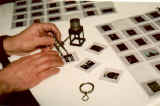
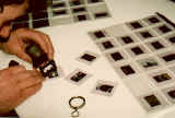
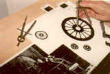
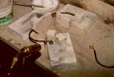
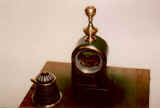
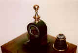
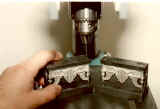
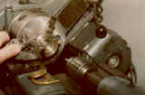
Examining and measuring details from some of the hundreds of slides taken of Bob Burns' original movie vehicle.
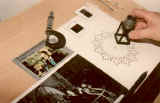
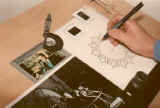
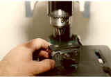
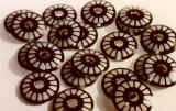
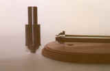
Finalizing Detail on the artwork for the "disc central boss" prior to printing.
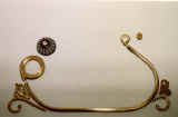
Checking the artwork for the nylon "end-caps" of the "Control Module;" forming jig for the horizontal solid brass "A-Frame."
Hard silver-soldering the "A-Frame;" jig forming the tubular brass "Side Frames."
Silver-soldering the brass castings to the side frames; jig for putting in the left and right hand "Double Bends" into the side frames.
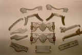
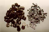
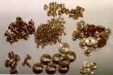
Cutting and drilling jigs for "Side Frames." One of the two sets of brass castings which will be silver soldered to the brass side frames, one at each end.
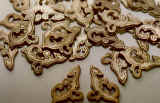
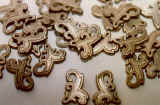
The other set of brass castings which will be silver soldered to the brass side frames, one at each end; the two sets of "Scroll" castings which are also soldered to the brass Side Frame.
The "Swans Neck" castings which are fitted to the chair; the brass "Faceplate" castings which are fitted to the Control Module.
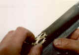
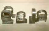
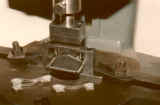
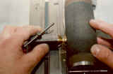
Sanding the concave curve on the casting to ensure an exact fit onto the control module; die-cast "motor housing" unit. Pair on the left side are "as cast;" that in the middle and on the right have had preliminary machining.
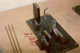
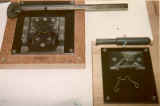
Drill jig for accurate positioning of base locating holes; drill jig for precision drilling of "transmission" and "electrode" holes.
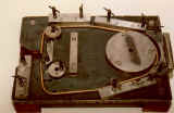
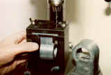
Same jig being used with a pendant drill to cut away the many rivet holes on this component; the painted and partially assembled motor housing, showing the major components which are attached to it.
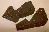
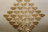
The fourteen white metal casings which form the "chair carcase;" precision stamping tool for pressing holes into the chair-arm underside, to locate the decorative "brass spheres" (not shown).
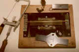
Two of the several drilling jigs used for the precision drilling of the chair components. Chair side rails above; back rail below.
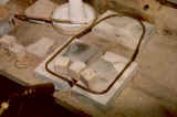
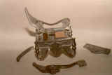
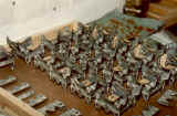
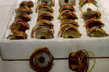
Partially assembled chair put together in a similar way to a conventional wooden chair with joints and locating "pegs;" a tray of partly built chairs.
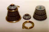
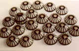
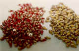
Making the "rebates" to locate the nylon "cones" and "domes" in the large brass "ring" casting; cone and dome; screen printed nylon cones assembly.
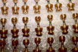
The two types of nylon cones, "cliche" printed, ready for assembly; where some of the previously mentioned parts go!
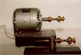
Steel "contrate" gears specially designed and made for the "Time Machine;" the "stepper" motor which drives the revolving disc, forwards and backwards through "time." 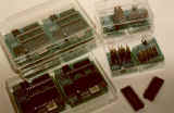 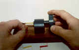
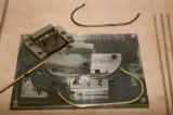
The specially designed microprocessor components which control the machine's functions. One large PCB and one smaller PCB are fitted into each model as is the all-important "chip;" simple winding jig for coiling the "electrode wire."
Precision machined and hand-painted brass electrodes; Swiss precision made routing tools for cutting molded edge on Swiss Pearwood base.
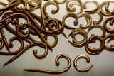
Three of the five jigs used to cut and bend square brass wire into the "scroll" form that fits below the control module.
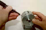
Two jigs for hand painting and polishing the transmission/gearbox unit before they are fitted to the motor housing; a tray of painted and polished components awaiting assembly.
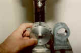
Precision sanding jig for ensuring accurate fit onto motor housing; some of the other "premium engineered" components. Don Brockway, October 21, 2000 (updated July 2, 2004) Return to Granite City
|